
Two Potential Components of Microgeneration
By Paul Spencer / The Rag Blog / July 7, 2008
Microgeneration may or may not present much of a solution for our increasing energy deficit; but it’s still fun, and it’s not counter-productive as a hobby, as long as we continue to do our personal duty of energy-use reduction and political agitation for renewable-energy generation. Within the category of microgeneration, there are a number of interesting inventions and ideas; but some of them make claims that are – well – unsubstantiated, if not physically impossible. For instance, some ‘rooftop’ wind turbine designers claim that a device that looks like an over-sized passive roof vent will supply a household’s energy needs. Ain’t gonna happen.
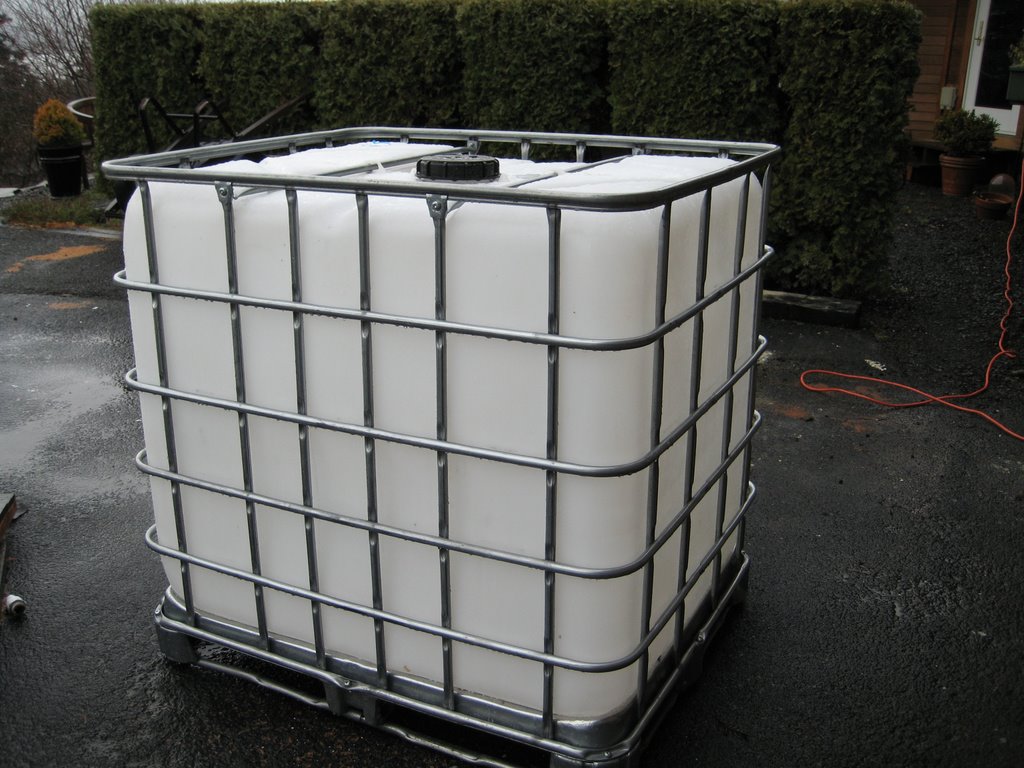
So – into that breach I leap. Last year I collected the pieces of an interesting puzzle – an experiment actually. Y’all might be interested in the results, when they become available. I should have some initial data this coming Winter. Ingredients (puzzle pieces): forty 6-volt, 180 amp-hour batteries; one 2.5 kilowatt, true-sine-wave, grid-tie inverter; 0.6 kw capability photovoltaic modules; five 4-feet by 12-feet, black rubber, solar-water-heating “pads”; two 275 gallon (U.S.) plastic water tanks; two ½ horsepower electric pumps; one water-to-air heat pump (5-ton capacity).
Here is an example of the water tank.
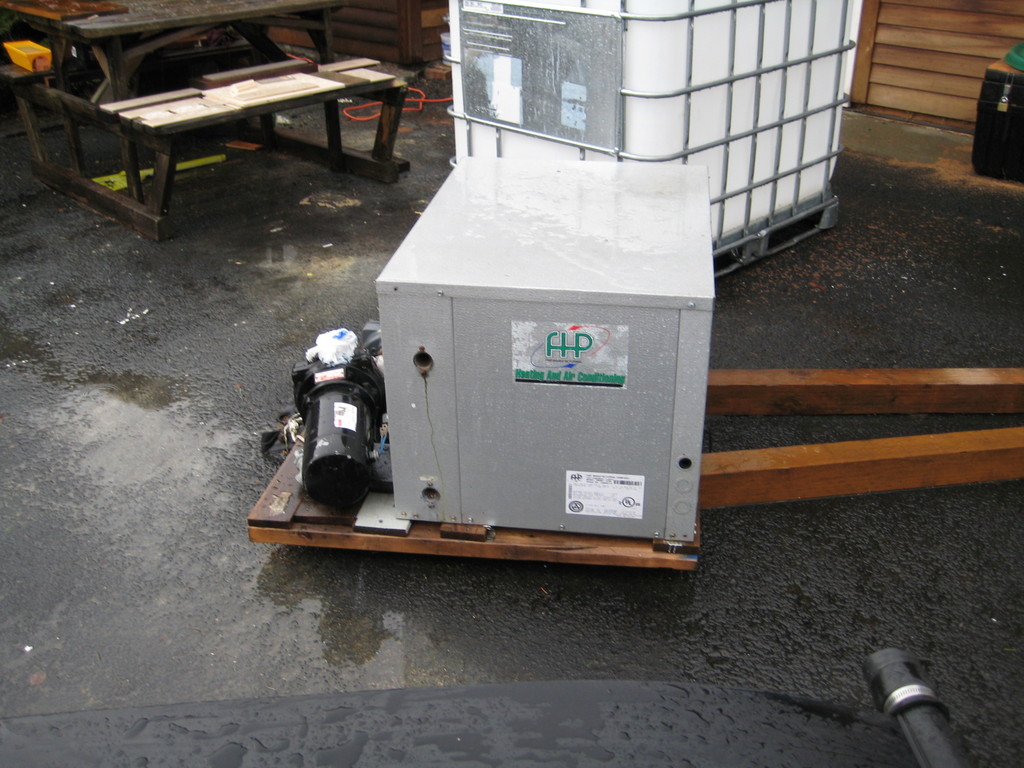
Here is the water-to-air heat pump (compressor/input-exchange end).
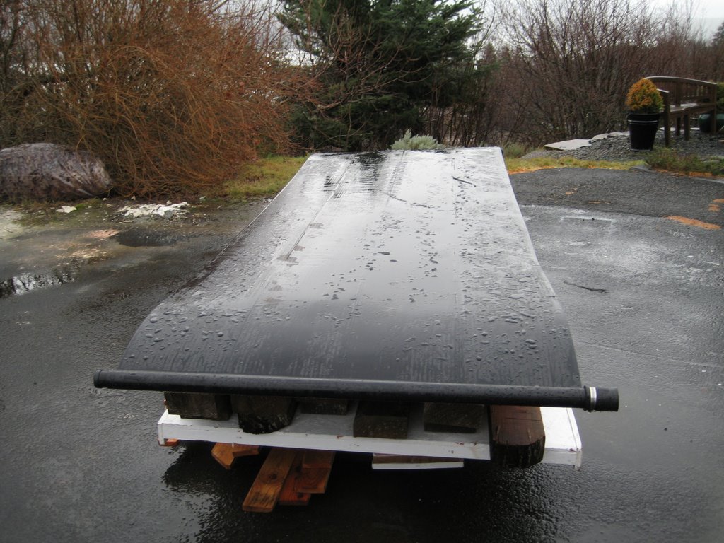
Here is one of the pads.
Here’s the theory, summarized: Water-to-air heat pumps use the well-known refrigeration cycle of expansion/compression [of a gas] to concentrate heat in one region of the machine and to remove heat from another region. For those who don’t know about the so-called geothermal heat pump system, it is typically based on pipes set about 1.7 meters deep in the ground, where soil temperature stays fairly stable at close to 10 degrees C in the temperate zones of the world. In Winter the refrigeration cycle is designed such that the heat pump pulls out some of the heat inherent in 10 degree water, sending, say, 5 degree water back into the pipes in the ground. The length of the piping system is calculated to permit the water to equilibrate at the ground temperature before returning to the heat pump. In Summer the system is valved such that the system reverses direction in terms of heat flow – the heated water goes out to the pipes in the ground. The piping systems are typically quite long, but the extent of the trenching can be reduced by digging wider trenches and looping the pipe as it is laid.
Another less-used system (that is also becoming more common) is to use black rubber pads with small channels fabricated into the length of the pads, manifolded into pipes running width-wise at either end of the pads, to capture solar-based heat in water flowing through these channels. In the U.S. swimming pools are sometimes warmed in the Spring and Fall by this method. Occasionally, these pads are used in conjunction with storage tanks to provide warm/hot water for ‘hydronic’ heating of floors – water-carrying tubes laid in thick mortar beds under tiles, for instance.
The idea/experiment here is to combine the heating via the black pads with a water-to-air heat pump. One ½ hp pump will drive the water from the storage tanks through the pads on the roof and back into the tanks. A second pump will take water from the tanks to the heat pump, when a house-interior thermostat demands hot (or cold) air.
Now we get to the particular arrangement.
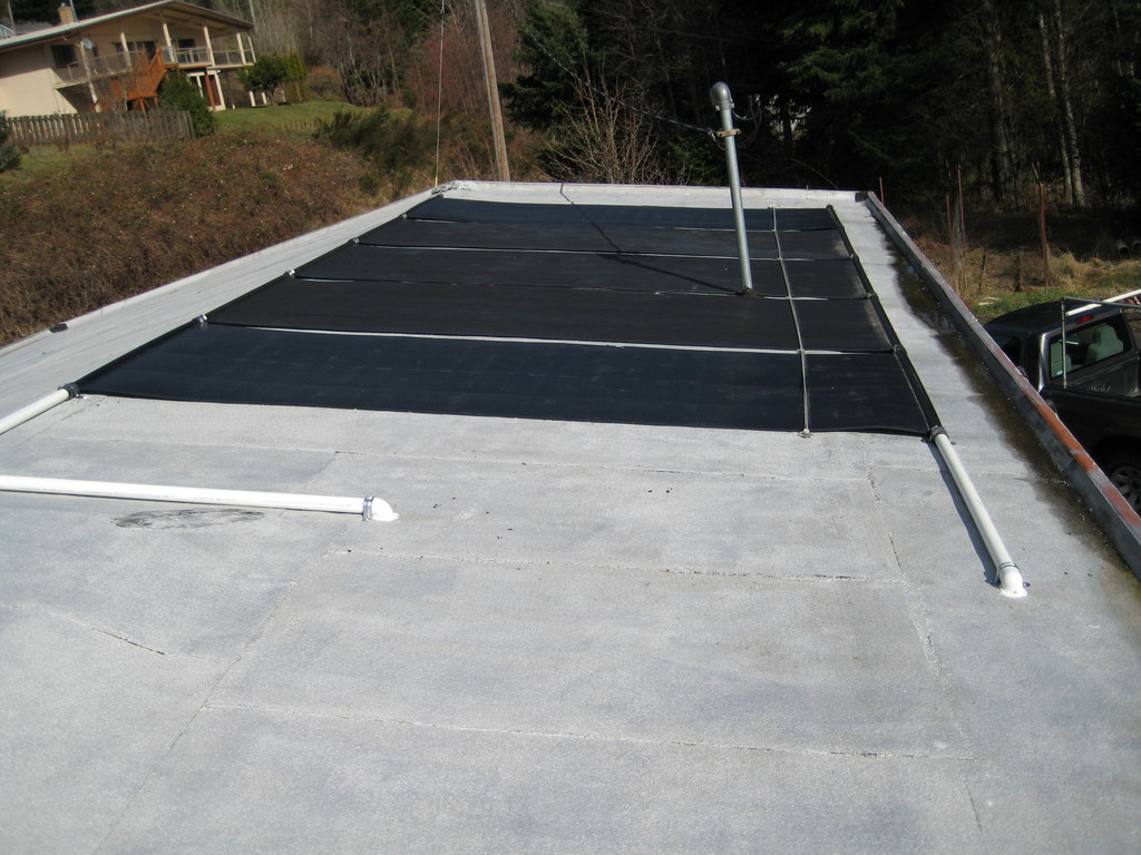
Here are 5 of the pads deployed and plumbed on my roof.
Here is the plumbing within the garage (directly under the pads).
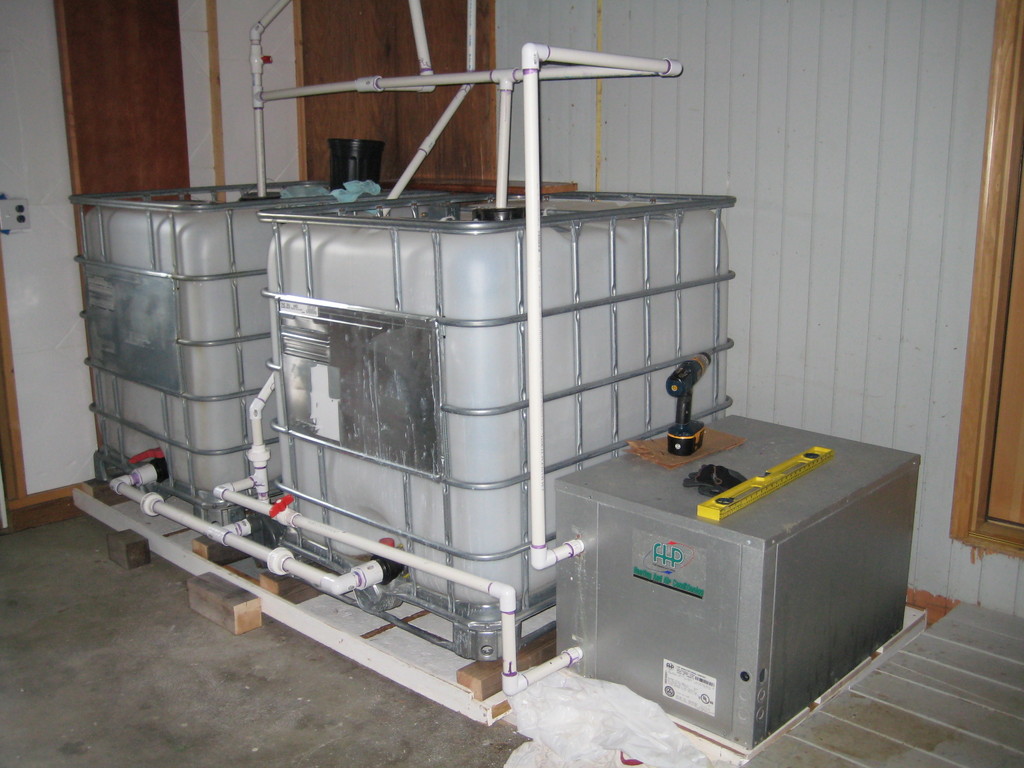
Next are a couple of close-ups of the plumbing by which you can see the basic arrangement. First, the outlets of the two tanks are in parallel and connected to a pump (in-between the tanks) that pushes water from the bottom of the tanks up to the lower-side connections of the pads on the roof.
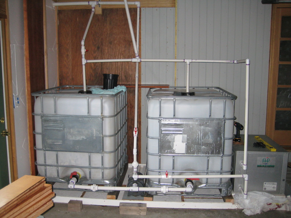
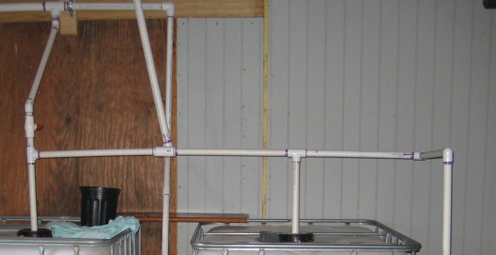
The pipe from the pump ‘tees’ to the water-to-air heat pump inlet. (From the heat pump outlet there is a pipe that goes to the return inlets in the caps on top of the tanks. These are loose-fitting to allow air pressure to stay equalized during pumping – and for ease of removal, if the caps need to be unscrewed for some kind of tank maintenance work.)
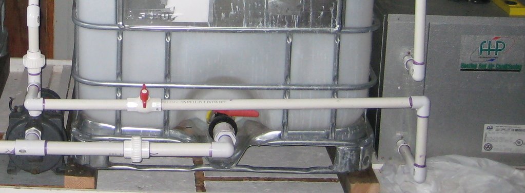
Returning water from the pads (hopefully, somewhat heated) is collected by a second pipe connected to the top ends of the pads. This bottom-to-top circulation keeps the water in the pads in contact with the pad’s tubes for best heat transfer. This collection pipe comes through the roof above the mid-point between the two tanks and ‘tees’ to two pipes lined up with the tanks’ caps (also ‘teed’ to the outlet pipe from the heat pump). The southern tank line (left side of picture) also is ‘teed’ with a return pipe from the water-pump-to-roof pipe, which is valved. This allows the water to be fully drained from the pads on the roof when the pump is not being operated. Without it, water would remain in the pads and the pipe to the pads, and, when outside temperatures go below freezing, the pipe and pads would be damaged by freezing water. In case it’s not clear, the valve is closed when the pump is operating; open when the pump is switched off.

As you can see there are several manual valves in the system. Initially, valves will be set by me for various periods of data collection. Eventually, the idea would be to put in servo- or electro-controlled valves that would be controlled by a computer set up to analyze water temperature, ambient outside temperature, and in-house temperature via sensors. The controls could be timed, too. It might be reasonable to have a daylight-sensing input, as well, since that should be the salient factor for heating, plus the salient counter-factor for cooling.
As I stated in my earlier diary my roof is a south-facing roof in the Columbia River Gorge, 65 kilometers east of Portland, OR. This geographical location is poor for solar insolation, and we have fairly strong winds that might cause loss of heat in the pads just from moving-air contact. Also, the roof is a 12:2, which means that it makes an angle of about 10 degrees to the horizontal. At my latitude the optimal roof angle would be more like 45 to 50 degrees to the horizontal as a compromise for the angle of the Sun in the sky from mid-Autumn to mid-Spring. Not the best situation for solar heating.
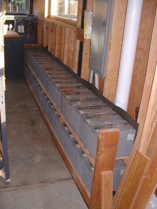
I have the forty 6-volt batteries in two rows, which will be arrayed in four parallel-circuit groups, which will then be hooked up in series, so that I’ll have a 24-volt system to match my inverter. The picture of the batteries shows them just after I had built the shelves and placed the batteries; they are now covered, but not connected. The inverter is mounted, but, obviously, not connected either.
Two pictures
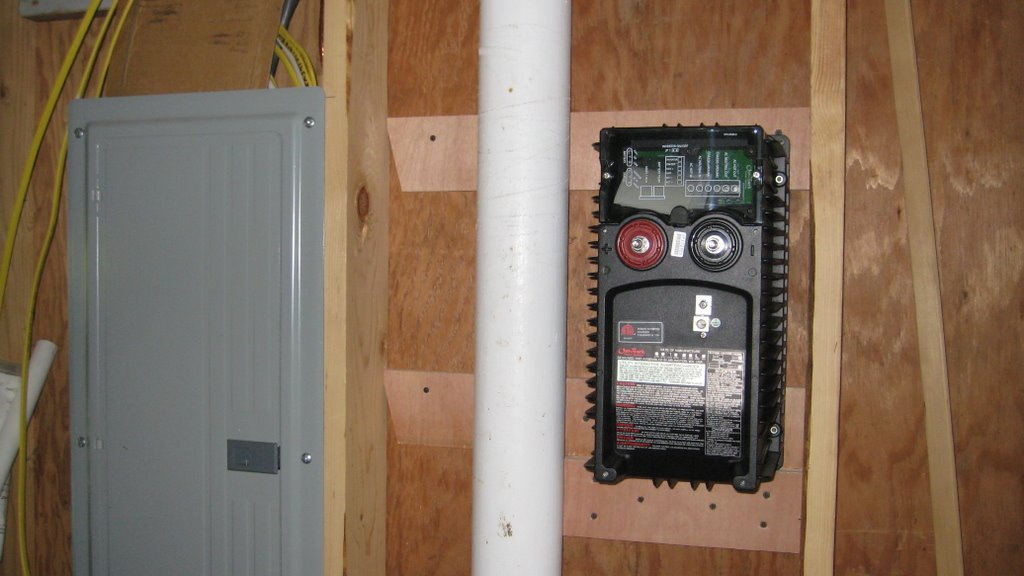
The inverter can make switching decisions such as: 1) if no exterior power (e.g., downed transmission lines), route from batteries to house demand; 2) if house demand is less than solar-based input, charge batteries; 3) if 2) and if batteries are charged, send to the exterior power grid (turn meter backwards).
I have 0.6 kw capacity of photovoltaics to install, but these should go up by mid-Autumn. At that point I’ll decide whether to buy more and whether to mount them on a structure that will, at least, allow me to vary the angle to the southern horizon.
That’s the update on the solar heating project. Here’s a diary in The European Tribune by ‘Marco’ on microgeneration, which said:
“There are an estimated 100,000 microgeneration units already installed in Britain.
“Nearly 90,000 of these are solar water heaters, with limited numbers of biomass boilers, photovoltaic panels, heat pumps, fuel cells, and small-scale hydroelectric and windpower schemes…
“But, with the right incentives, nearly one in five buildings in Britain would effectively become mini power stations, feeding electricity into the grid, or generating enough to be largely self-sufficient. Some of the greatest gains would be in combined heat and power units which are suitable for large blocks of flats, estates and businesses.
“In Britain, as in the United States, zoning laws and regulations are obstacles that are blocking greater investment of microgeneration of power, especially with wind turbines. Britons, including Prime Minister Gordon Brown, ‘have all had applications to erect wind turbines on their roofs turned down by planning officers.'”
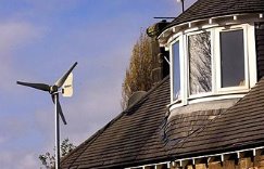
Sorry, but this just makes sense. Small, propellor-type turbines have a high rotational speed, which makes them a potential disaster for birds and bats, at least. Beyond that, there are critical issues of manufacture (balancing, for instance), installation, maintenance, and monitoring (for fatigue failure among other conditions).
As one reader commented:
“Microgeneration should not include windpower at this time in urban areas. Virtually no urban areas of the world have enough of a wind resource to sustain the development of such an industry. Even windy San Francisco can’t sustain residential scale wind turbines except right on the coast, or the highest elevations. Better that neighborhoods be allowed to invest in commercial developments where the winds are strong.”
Another reader raised a particularly good point:
“However, there is also the question of …
… sweat equity. In a system where large numbers of people cannot reliably expect to sell as much labor as they are willing to offer to the market, microturbines of the kind that have half the generator mechanism expoxied into the turbine might have a cash cost that is appealing for some, even if the full economic cost including the notional cost of labor would make it appear uneconomic.
“When it is reducing total demand from the grid, it is replacing electricity sold at retail … if net metering is in effect, this is topped up during surplus generation periods by selling surplus power onto the grid.”
So – the second part of this diary – how about VAWT (Vertical Axis Wind Turbines) as a kind of hobby with low cost, low risk, and modest payback? I know the efficiency arguments concerning vertical-axis vs. propellor-style turbines, and they are likely correct, but take a look at this just for fun:
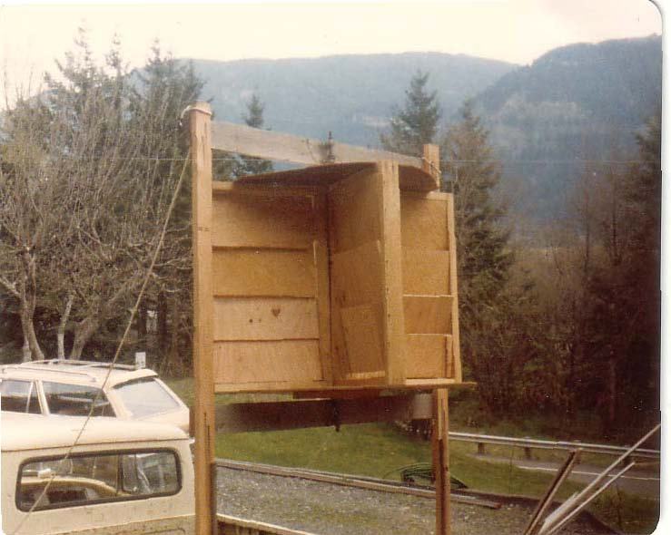
I suppose that it’s not self-explanatory, even in graphic form, but this device closes the vanes on the half of the cycle where the wind is driving the ‘wall’ and opens the vanes on the half of the cycle when the wind is opposing rotation. Does it actually perform as described? This is a picture from 1982 of my homemade model mounted in the back of my ’62 IH pickup truck. (I only drove used ‘cornbinders’ from county surplus sales from the late-’60s to the early ’80s. Larry Caroline introduced me to them.) I drove it down the road, and the ‘mill’ performed exactly as described. It started turning at about 5 mph, vanes started lifting and closing at about 7 mph, and it was spinning at a rather frightening rate when I hit 15 mph (and the vanes were still opening and closing, clacking away – no, it wasn’t my cornbinder’s valves). I didn’t dare go any faster than that, because I could also see that my lashing job wasn’t going to keep the device in my truck, if I didn’t slow down.
OK – this was an unbalanced model made out of pieces of stuff that I found in my garage, and the wood vanes made a fair racket. Now it’s time for me to make a more usable (and bigger) model out of materials that will endure and operate quietly. This time I won’t go for junkyard chic. In fact I will use materials that will test the cost factor for this design.
I predict that the cost for this type of device will be low, even with caging to prevent contact with anything larger than a dragonfly. As to conversion efficiency, I visualize a fairly reasonable torque that might be converted to high-speed rotation of an alternator via a simple belt drive – all right on the ground, where it’s relatively easy to support, to maintain, to replace, to whatever. Low wind-speeds due to ground interface? Probably, but the device should at least be responsive to changes in wind direction, however frequent and unpredictable. Y’all know the arguments, but this observation might be the clincher for going forward. This device can be made out of the “stuff in my garage”; it’s not a difficult job at all. If it turns out to be inexpensive to boot, what’s to lose?
What have y’all got for show-and-tell?
Go here for Paul Spencer’s all the entires so far “The Earth: Love It or Lose It” series on The Rag Blog.
The Rag Blog